The Critical Role of Electrical Symbols in Modern Engineering
The world of engineering relies heavily on a universal language. This language ensures that complex ideas travel across borders without confusion. Consequently, professionals use specific icons to represent components. These icons are known as electrical symbols. They act as the alphabet for electricians and engineers worldwide. Without them, wiring a simple circuit would become a chaotic guessing game. Imagine trying to build a house without a blueprint. The process would be dangerous and inefficient. Therefore, these symbols provide a necessary structure. They allow one engineer in one country to design a system. Then, another engineer in a different country can build it perfectly. This universality saves time and reduces errors significantly.
Furthermore, safety is a paramount concern in this industry. Electricity is invisible and inherently dangerous. A small mistake in wiring can lead to catastrophic failures. Fires and electrocution are real risks in bad designs. However, standardized symbols mitigate these risks effectively. They communicate exact specifications clearly. For instance, a symbol dictates the exact type of switch needed. It also shows the precise path of the wiring. As a result, technicians know exactly what to do. They do not need to guess the voltage or the current type. This clarity protects both the worker and the future user of the system.
In addition, the year 2026 brings new technological advancements. Systems are becoming more complex and integrated. Smart homes and renewable energy sources are now standard. Therefore, the need for clear documentation is higher than ever. Old methods of sketching by hand are obsolete. We now rely on digital precision. Consequently, understanding these symbols is a fundamental skill. It is not just for engineers anymore. DIY enthusiasts also benefit from this knowledge.
Decoding Basic Electrical Symbols for Beginners
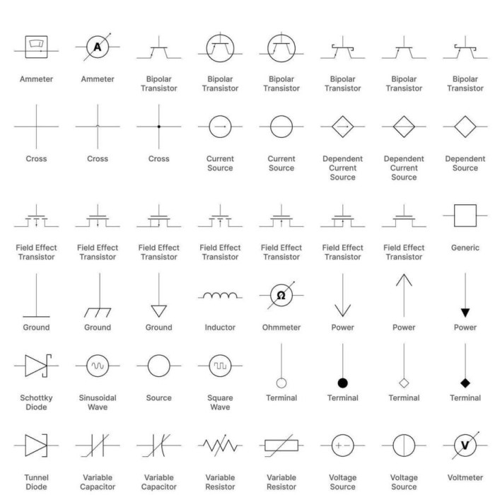
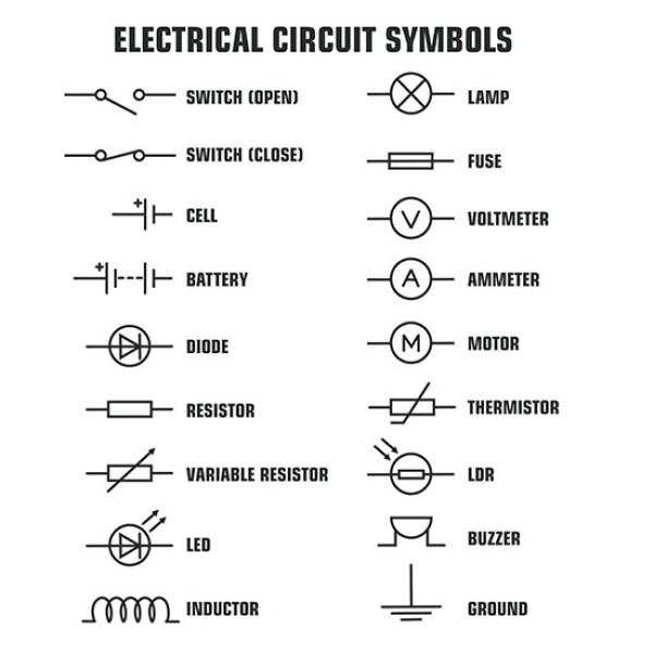
Every journey begins with a single step. In electronics, that step involves learning the basic components. These are the building blocks of any circuit. Therefore, recognizing them is crucial for beginners. First, we have the resistor symbol. It looks like a zigzag line. This component limits the flow of current. It is essential for protecting sensitive parts. Next, consider the capacitor. Its symbol consists of two parallel lines. Sometimes one line is curved. This part stores electrical energy temporarily. It acts like a small battery within the circuit. Consequently, you will see it in almost every electronic device.
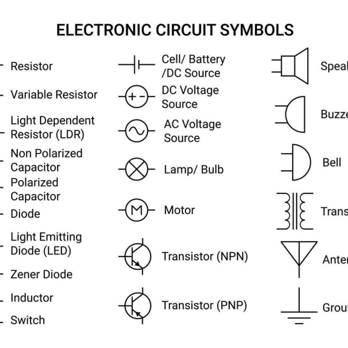
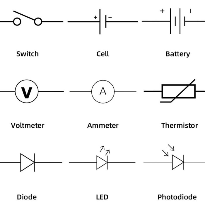
Moreover, switches are vital for user control. The symbol for a switch is a break in a line. It looks like a door that can open or close. When the door is closed, the current flows. When it is open, the circuit breaks. There are many types of switches. For example, a push-button switch differs from a toggle switch. However, the basic concept remains the same. Another fundamental symbol is the ground. This symbol looks like a triangle made of lines. It provides a safe path for excess current. This path prevents shocks and damage. Therefore, it is a critical safety feature. You must never ignore the ground symbol.
In addition, power sources need identification. The battery symbol uses long and short parallel lines. The long line represents the positive terminal. The short line represents the negative terminal. Often, circuits use DC or AC power supplies. Their symbols are distinct and easy to recognize. A circle with a wave inside signifies an AC source. A straight line inside a circle usually means DC. Understanding these distinctions prevents accidents. For instance, connecting a DC motor to an AC source causes failure.
Interpreting Wiring Diagrams and Schematic Layouts
Reading a diagram is different from reading a book. You do not read it linearly from left to right. Instead, you must analyze the flow of power. Therefore, understanding the layout is key. A schematic diagram shows the logical function of a circuit. It does not show the physical arrangement of the wires. Consequently, the lines on the paper represent connections. They do not represent the actual length of the wire. This distinction confuses many beginners. They might try to replicate the exact layout physically. This approach often leads to a mess of wires. Instead, you should focus on the connections. Trace the path from the power source to the ground.
Furthermore, wiring diagrams are slightly different. They show the physical location of components. For example, a wiring diagram for a car shows where the sensor is. It also shows the color of the wires. This information is vital for repairs. Mechanics use these diagrams daily. On the other hand, electrical schematic symbols help in design. Engineers use them to test the logic of the circuit. They simulate the flow to check for errors. Consequently, both types of diagrams serve specific purposes. You must choose the right one for your task. If you are designing a circuit board, use a schematic. If you are installing a ceiling fan, use a wiring diagram.
In addition, identifying nodes and junctions is important. A node is a point where two or more wires connect. Usually, a dot represents this connection. If two lines cross without a dot, they do not connect.
Advanced Electrical Symbols for Complex Systems
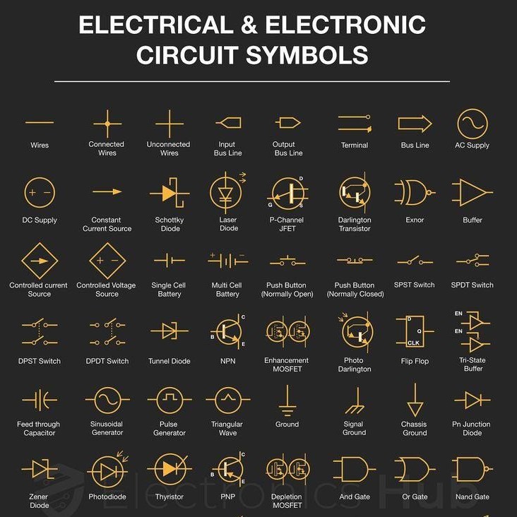
As technology advances, so do the symbols. Modern circuits are not just about resistors and capacitors. They involve complex logic gates and integrated circuits. Therefore, professionals need an advanced vocabulary. Logic gates are the brains of digital electronics. They process binary signals. The AND gate symbol is a flat-backed shape. The OR gate has a curved input side. These shapes tell engineers how the circuit thinks. For instance, an AND gate requires two inputs to turn on. An OR gate needs only one. Consequently, these symbols dictate the logic of computers.
Moreover, transformers are common in power systems. Their symbol consists of two parallel coils. This component changes voltage levels. It steps up voltage for transmission. Or, it steps down voltage for home use. Transformers are massive industrial devices. Yet, their symbol is simple and elegant. Similarly, motors and generators have specific icons. A circle with the letter “M” represents a motor. A circle with a “G” stands for a generator. Sometimes, the symbol includes winding details inside the circle. These details show the type of motor. For example, a shaded pole motor has a distinct marking. Therefore, these nuances help in selecting the right replacement part.
In addition, integrated circuits (ICs) are prevalent. These are complex chips with millions of transistors. It is impossible to draw every transistor. Therefore, engineers use a rectangle symbol. It has pins coming out of the sides. Each pin has a number and a function label. You must refer to the datasheet for details. The datasheet explains the internal structure. Consequently, reading an IC diagram requires research.
International Standards for Electrical Drawings
Global trade requires a unified standard. An engineer in Japan must understand a diagram from Germany. Therefore, international organizations set rules. The International Electrotechnical Commission (IEC) is the main body. They publish the IEC 60617 standard. This standard defines graphical symbols for diagrams. It covers a vast range of components. Most countries adopt these standards. Consequently, they ensure consistency worldwide. However, some regions still use their own standards. The United States often uses ANSI standards. The American National Standards Institute has slightly different symbols. For example, the resistor symbol in the US is a zigzag. In IEC standards, it is a simple rectangle.
Furthermore, understanding these differences is vital. If you work on imported machinery, you will see IEC symbols. If you work on older American equipment, you see ANSI symbols. Therefore, you must be bilingual in this sense. You need to know both sets of electrical symbols. This skill prevents costly mistakes. Imagine replacing a resistor with the wrong tolerance. The machine might fail prematurely. Thus, the symbol conveys more than just identity. It also conveys the standard of quality. Moreover, the IEEE standards govern how we document these symbols. They provide guidelines for reference designation. This system labels every part uniquely. For instance, a resistor might be labeled “R1”. A capacitor might be “C1”. This labeling makes troubleshooting easier.
In addition, color codes are a form of standardization. While not a drawn symbol, they are a visual code. Resistors have colored bands. These bands indicate resistance value. Similarly, wiring has color codes. In the US, black is a hot wire. Green is a ground wire. In other countries, these colors differ. For example, Europe uses brown for live wires.
Essential Safety Symbols and Warning Labels
Safety is the most important aspect of electricity. Electrical hazards can be invisible and deadly. Therefore, safety symbols are bright and bold. They act as warnings. The most common symbol is the lightning bolt. It indicates high voltage. It warns you to stay away. This symbol often appears inside a yellow triangle. The triangle is the universal sign for caution. Consequently, you should never ignore it. Another vital symbol is the “Risk of Electric Shock.” This symbol usually shows a hand with a lightning bolt. It tells you that touching the part is dangerous.
Moreover, mandatory action symbols are blue circles. They tell you what you must do. For example, a symbol might show safety gloves. This means you must wear insulated gloves. Another might show safety goggles. These instructions are not suggestions. They are legal requirements in many workplaces. Therefore, ignoring them can lead to injury. It can also lead to legal trouble. Furthermore, prohibition symbols are red circles with a diagonal line. They show what you cannot do. A common one is “No Access.” This keeps unauthorized people away from danger zones.
In addition, fire safety symbols are relevant. Electricity is a leading cause of fires. Symbols for fire extinguishers are crucial. You must know which extinguisher to use on electrical fires. A Class C fire involves electrical equipment. Using water on an electrical fire is fatal. Therefore, the symbol will show a non-conductive agent. These symbols guide you during emergencies. When panic sets in, you rely on visual cues. You do not have time to read long instructions. Thus, these symbols save lives. They are designed for instant recognition. Every worker should memorize them. It is a basic part of job site safety.
Digital Tools for Reading Electrical Symbols in 2026
Technology has changed how we interact with diagrams. In 2026, paper blueprints are becoming rare. Instead, we use digital formats. Therefore, new tools have emerged. CAD (Computer-Aided Design) software is the standard. Programs like AutoCAD Electrical simplify the process. They contain vast libraries of symbols. You simply drag and drop the symbol you need. The software ensures the symbol is standardized. Consequently, the risk of drawing errors decreases. These tools also check your circuit logic. They can simulate the flow of electricity. This feature catches design flaws early. It saves money and time on prototypes.
Furthermore, mobile apps are now powerful tools. You can take a photo of a diagram. The app identifies the electrical symbols instantly. It uses augmented reality (AR) technology. You look at a panel through your phone camera. The app overlays the schematic on the screen. It highlights wires and components. This technology is revolutionizing maintenance. Technicians do not need to carry bulky manuals. All the information is in their pocket. Therefore, AR makes work more efficient. It also reduces the learning curve for apprentices. They can learn on the job with digital assistance.
In addition, cloud collaboration is key. Teams work from different locations. An engineer in New York can update a diagram. An electrician in London sees the changes instantly. This connectivity ensures everyone works from the latest version. Consequently, miscommunication becomes a thing of the past. Version control is automatic. You can see who changed what and when. This transparency is vital for large projects. Thus, digital tools do more than just draw. They manage the entire project lifecycle. They integrate the symbols into a broader workflow. Mastering these tools is now a prerequisite for the job.
The Future Outlook for Electrical Documentation
The field of electrical engineering is evolving rapidly. As we move further into the 2020s, the pace quickens. Therefore, the way we use symbols will change. Automation is a major driver. Machines are designing circuits now. Artificial Intelligence (AI) can optimize a layout better than a human. AI uses standard symbols to generate designs. Consequently, the human role shifts from drawing to supervising. We check the AI’s logic. We ensure the design meets safety codes. Thus, the fundamental meaning of the symbols remains. However, the method of their application changes.
Moreover, the complexity of devices increases. The Internet of Things (IoT) connects everything. A light bulb is now a computer. It has a wireless radio and sensors. Therefore, we need new symbols for these smart components. Traditional symbols do not cover data flow adequately. We see a rise in hybrid diagrams. They show both power and data lines. This requires a new way of thinking. Engineers must understand both electrical and network engineering. Consequently, educational curriculums are adapting. Future electricians need a broader skill set. They must be as comfortable with data as they are with voltage.
In addition, virtual reality (VR) plays a role. Imagine putting on a headset. You walk through a virtual building. You see the wires inside the walls. The symbols float next to the components. This immersive experience helps in training. It also helps in complex troubleshooting. Therefore, the flat 2D diagram becomes a 3D reality. This shift will redefine technical documentation. It makes the abstract concrete. As a result, safety and understanding improve. We are entering an exciting era. The humble symbol is the foundation of this future. It continues to be the silent language of innovation.
Conclusion
In summary, the language of engineering is visual. It transcends spoken words and borders. Mastering electrical symbols is essential for anyone in the field. It ensures safety, efficiency, and clarity. We have explored the history, the basics, and the future. We also looked at the digital tools that aid us. As technology advances, these symbols will adapt. However, their core purpose remains unchanged. They allow us to harness the power of electricity safely. Therefore, keep learning and stay updated. Your knowledge of these symbols protects lives. It also powers the modern world.